UF2 Batch Flasher
When you want to scale a project, one simple way to make it happen is to make it modular. However, making things modular in software is easy, as you can program some software to do something as many times as you want. However, when dealing with hardware, this is yet another problem to be faced.
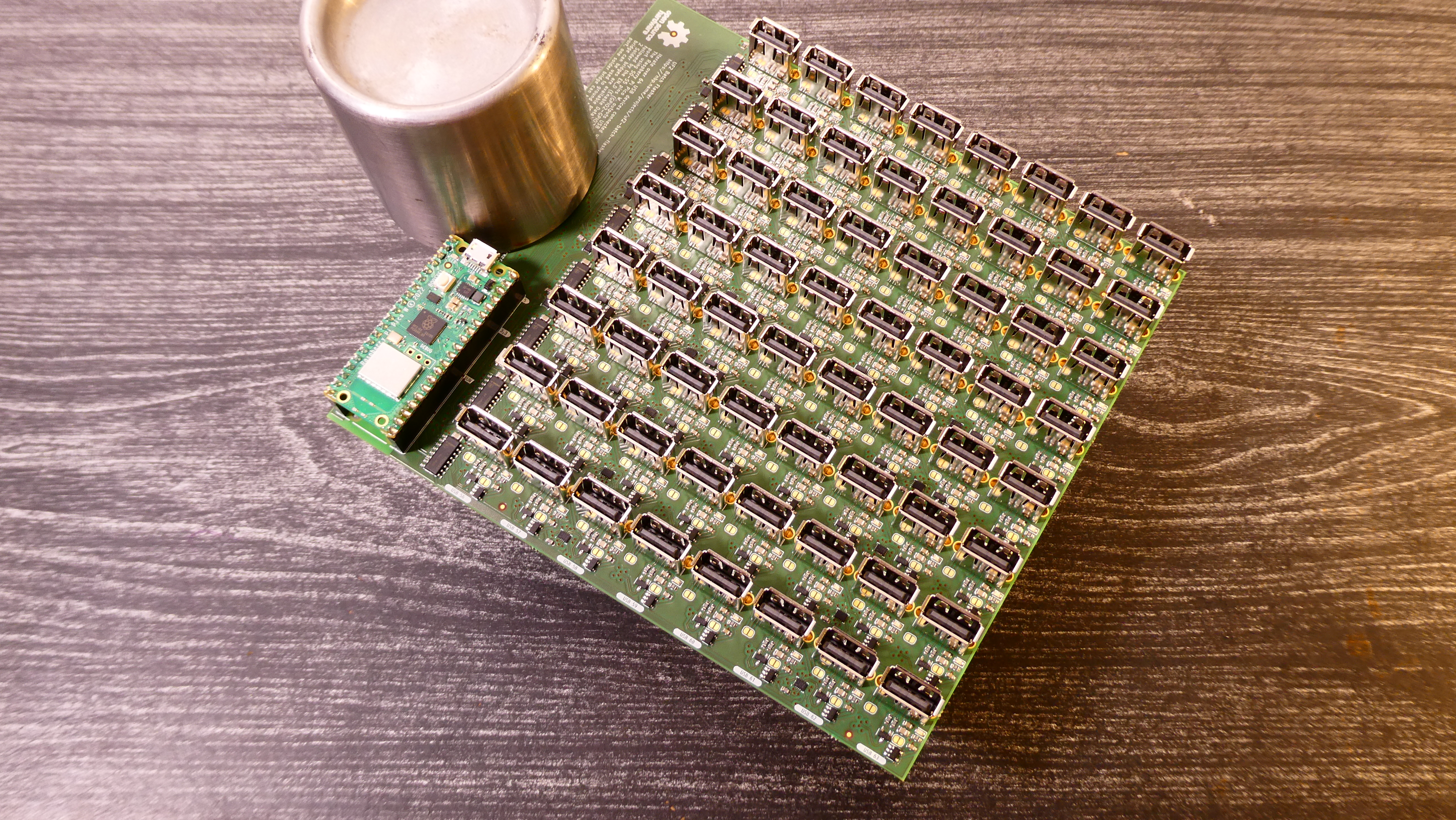
The UF2 Batch Flasher is meant to provide a way to loop over up to 64 devices, in order to flash all the 64 devices with a single UF2 image. Using a Raspberry Pi Pico, and 64 USB A ports, the RP2040 will select one port at a time, and copy the transmitted image to each device.
The alternative is to find the next cable, find the board at the end of it, press a button, plug the cable while pressing the button, type a command / drag a file over, unplug the device and repeat this 63 times. Not only this error prone but this is time intensive and would probably take half an hour to iterate over that many devices manually.
Motivation
This project came up as a need for another project, for which 60 Raspberry Pi Picos are already reserved for prototyping it. At the end, the UF2 Batch Flasher should be integrated within this other project. In order to reduce chances of failures, while prototyping, splitting the functions in different sub-projects made sense.
Thus the UF2 Batch Flasher is a way to reduce the cost of unrelated failures while providing a versatile platform for experimenting with a large set of devices.
Overview
This project is designed around 3 main components. The Raspberry Pi Pico W, the FSUSB74 which is a 4 way-switch for USB signals and 74HC238 which is a selector.
The RP2040, the microcontroller of the Raspberry Pi Pico, is programmed to set the pins of both the 74HC238 and the FSUSB74 to select a single USB port among the 64. In addition to that, A data-enable pin and a power-enable pin are used to cut off the switches and turn off the power, even if the port is selected.
TinyUSB is used to implement a USB host port with the pins 0 and 1 connected to the selected USB device. The UF2 process is a device feature, as the host only sees it as a Mass Storage (MSC) device. Thus testing can be done with a USB flash drive.
In the case where the flashed device is also a RP2040, then there is a neat feature which implies that one does not have to press the Boot-select button. This is achieved in software by selecting a Baud Rate of 1200 Hz. Once set, the RP2040 will automatically reboot in Boot-select mode.
The image to be flashed is transmitted over Wifi, as well as the stdout debug information and the last recorded status of each USB device. A Web server is implemented using LwIP, which serves a web page which contains the high level logic and sends commands over, such as selecting each USB and transmitting the image to be flashed.
The Making Of
No surprises that such electronic design is based of 2 things, one which is the 4 layer circuit board and the other which is the software which is flashed on the Raspberry Pi Pico.
The Board
Selecting Components
One of the challenges about making a PCB is knowing what has to be achieved, looking in the part collection which one is the best for the task. Many components could be used to implement a USB switch, but ideally one should look for a component which toggles both data lines at the same time.
Surprisingly, it was difficult to find a single component which handled the data line and the power line. At the end, settling on the AP22804AW5-7 for regulating the 5V power and on the FSUSB74 for switching the data lines.
Having both separated is potentially necessary as some might have noticed on male USB A connectors that the data connectors are shorter than the power connectors.
The FSUSB63 documentation recommends the usage of 1pF TVS/ESD with a 2.2 Ohm. Thus, each USB port is protected by a PESD2USB3UVT which is used to let go if there are any spikes on the data lines. However, there is no protection in the case of surges from the GND or from the 5V power line.
To enable the AP22804AW5-7, we have to pull-up the enable pin. Given that the Pico does not have 64 GPIO, this is achieved using the 74HC238 which switches on the select line, in a similar way as the FSUSB74 selects a given pair of data lines.
The 74HC238 has 8 outputs whereas the FSUSB74 has 4, which implies that we have effectively 2 trees of components used to toggle a unique USB port at a time. Fortunately both can be used to decompose 64, which implies that no output pins are wasted. However, caution should be used to correctly map the select pins across both, such that we correctly toggle the power and data line of the same USB port. Thus using the high select bit near the microcontroller, and the lowest select bits when closer to the USB port, as well as using the same ordering on the decoded/selected inputs pins.
Capacitors
The USB specification requires that a 120 µF electrolytic capacitor is used per USB port. However, placing these components on the board was taking most of the space. Obviously these capacitors are not used either in small and cheap USB hubs that are found everywhere.
Apparently electrolytics capacitors can be replaced by multi-layer ceramic capacitors (MLCC). The reasoning is that Electrolytic capacitors have a higher internal resistance (ESR), thus one should have a higher capacitance to filter the same frequencies. As MLCC have a much lower ESR, one can pick a capacitor with a smaller capacitance.
Still there is a trap, MLCC capacitors have a reduced capacitance when used with direct current (DC), which is the case of the 5V power line for powering USB devices.
Bill Of Material
Except for the USB cables, all the components are sourced from Mouser, and the PCB is ordered from Aisler for 118.20€ (x3) with a stencil at 34.09€ as well as a 2.02€ donnation for KiCad.
| Qnty | Value | Description | Vendor | Price |
|---|---|---|---|---|
| 73 | 0.1uF | Unpolarized capacitor | eu.mouser.com | 1.60€ |
| 21 | 1nF | Unpolarized capacitor | eu.mouser.com | 0.27€ |
| 64 | 1uF | Unpolarized capacitor | eu.mouser.com | 0.90€ |
| 64 | 22uF | Unpolarized capacitor | eu.mouser.com | 3.60€ |
| 64 | Green | Light emitting diode | eu.mouser.com | 8.45€ |
| 64 | PESD2USB3UVT-QR | 3.3V dual ESD | eu.mouser.com | 12.60€ |
| 64 | USB_A | USB Type A connector | eu.mouser.com | 29.50€ |
| 1 | 10 kOhm | Resistor | eu.mouser.com | ~5.00€ |
| 64 | 120 Ohm | Resistor | eu.mouser.com | 5.00€ |
| 128 | 2.2 Ohm | Resistor | eu.mouser.com | 5.00€ |
| 1 | CUI_TS20 | Normally-open tactile switch | eu.mouser.com | 0.29€ |
| 21 | FSUSB74 | High-Speed USB Multiplexer / Switch | eu.mouser.com | 18.88€ |
| 9 | 74HC238 | 3-to-8 line decoder/multiplexer, DIP-16/SOIC-16/SSOP-16 | eu.mouser.com | 2.94€ |
| 1 | RaspberryPi_Pico_W | RP2040 dual-core Arm Cortex-M0+, 264kB SRAM, Infineon CYW43439 2.4GHz 802.11n wireless LAN | eu.mouser.com | 5.58€ |
| 64 | AP22804AW5-7 | Power switch | eu.mouser.com | 21.06€ |
Only considering all the parts, this makes a total of 270€ without taxes, the delivery taxes, the solder paste, the USB cables, nor the devices to be connected at the other end.
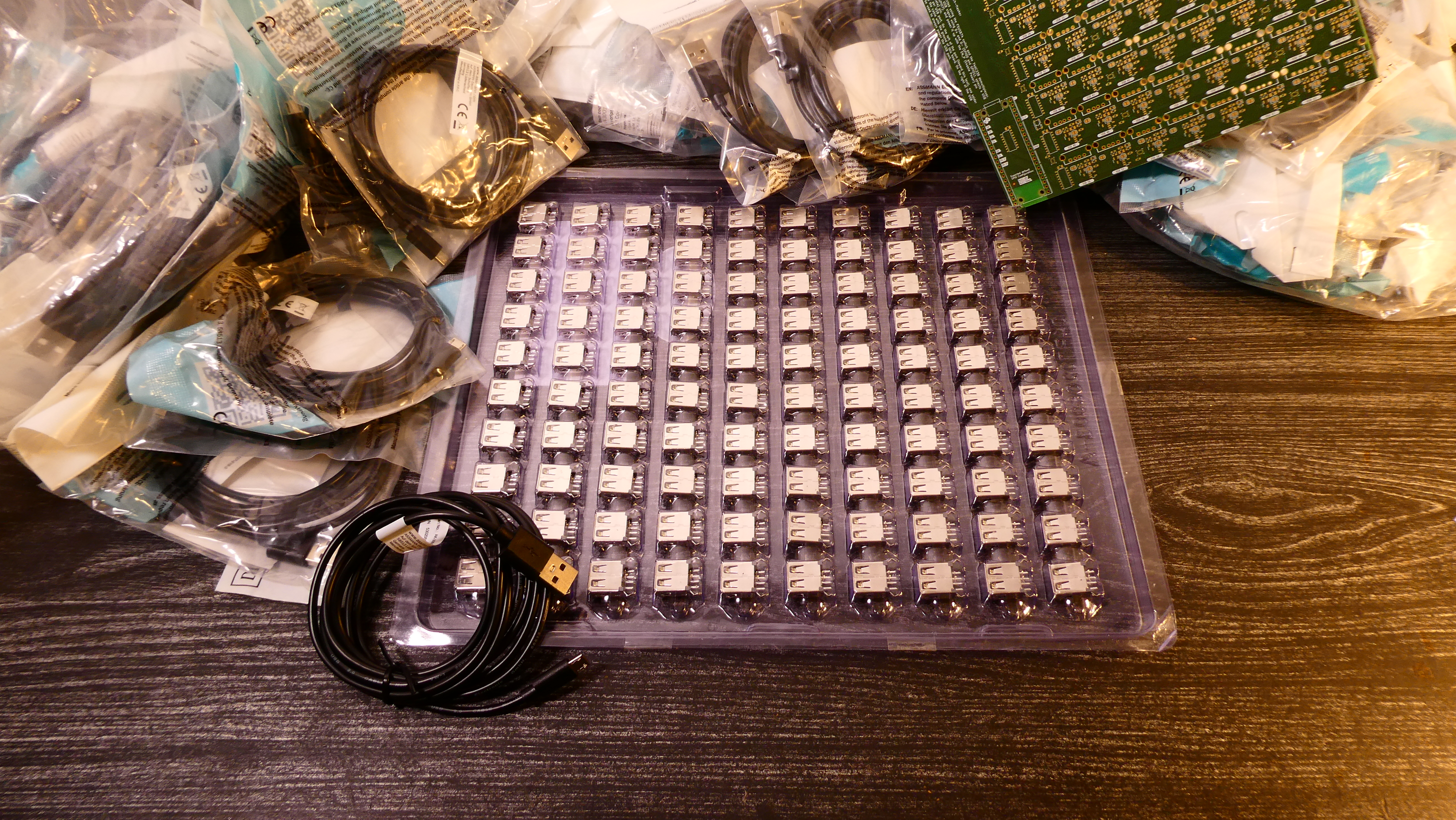
Most people do not have 64 USB cables resting in a closet, and finding the cheapest USB cable on Amazon would not help with the budget of this project. However Amazon can hint where one might look for. In this case TME and Assmann have a large collection of USB cables of various kinds and qualities, such as the AK-300127-018-S.
Beware that the price is aligned with the quality of the cable. At this price tag do not expect a long shielded cable capable of USB 3.0 speed. On the other hand, the PIO emulated USB port would not go at USB 3.0 speed either, but the 1.8m might be a problem for some applications. Be aware that all the 64 connected devices would be at a cable-length of the UF2 Batch Flasher.
Placing Components
The placement of components on the board is at the scale of being painful if done by hand, as there are more than 600 surface mounted components, for which solder paste and a reflow oven are recommended.
Having a LumenPnP from Opulo is definitely helpful, and using some feeders for the 2.2 Ohm resistors is a nice luxury. Except that LumenPnP feeders do not yet have a direct feedback of the tape position and there is a backlash which can cause important variations in the picking position. This is problematic enough that after picking a few of components, the picking procedure would miss the pocket.
After trying multiple mechanical solutions such as adding pressure or drag to the tape, a software solution came up as the best option. The software will look at the reference holes of the tape and compute the picking location. While this adds latency, this is less of a problem than dealing with every wrong pick. This extra vision is implemented in a fork of OpenPnP. Later, support of 0402 components should be added, as well as a way to skip using vision when the picking location's variance becomes small enough.
Also, verifying that you are using the same version of the fiducial placement helps avoid errors and reduce the time needed to watch for misplaced components.
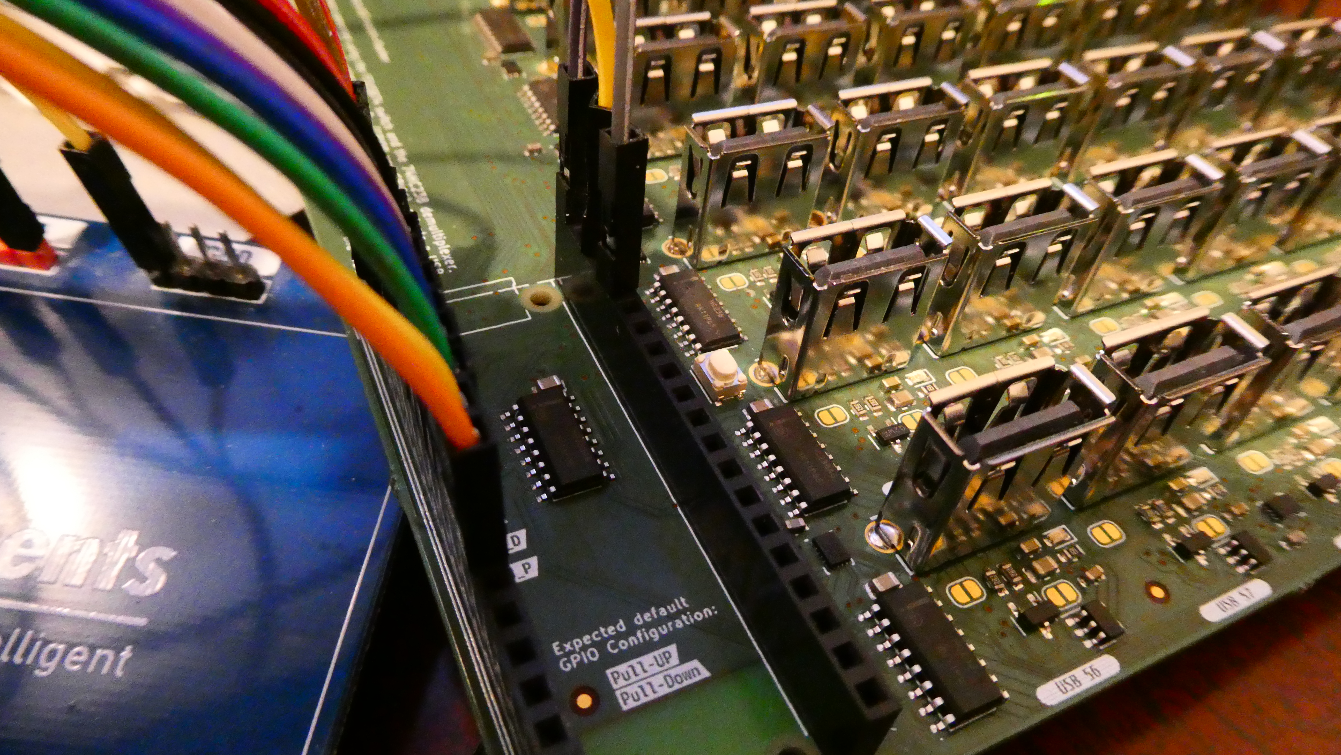
Fixing QFN Solder Bridges
Before soldering the vertical USB ports, have a look at the FSUSB74 in case of short circuits. A short on the D+ / D- pins with the ground or 3.3V pins is possible and this might cause too much current, where the limit is at 20 mA.
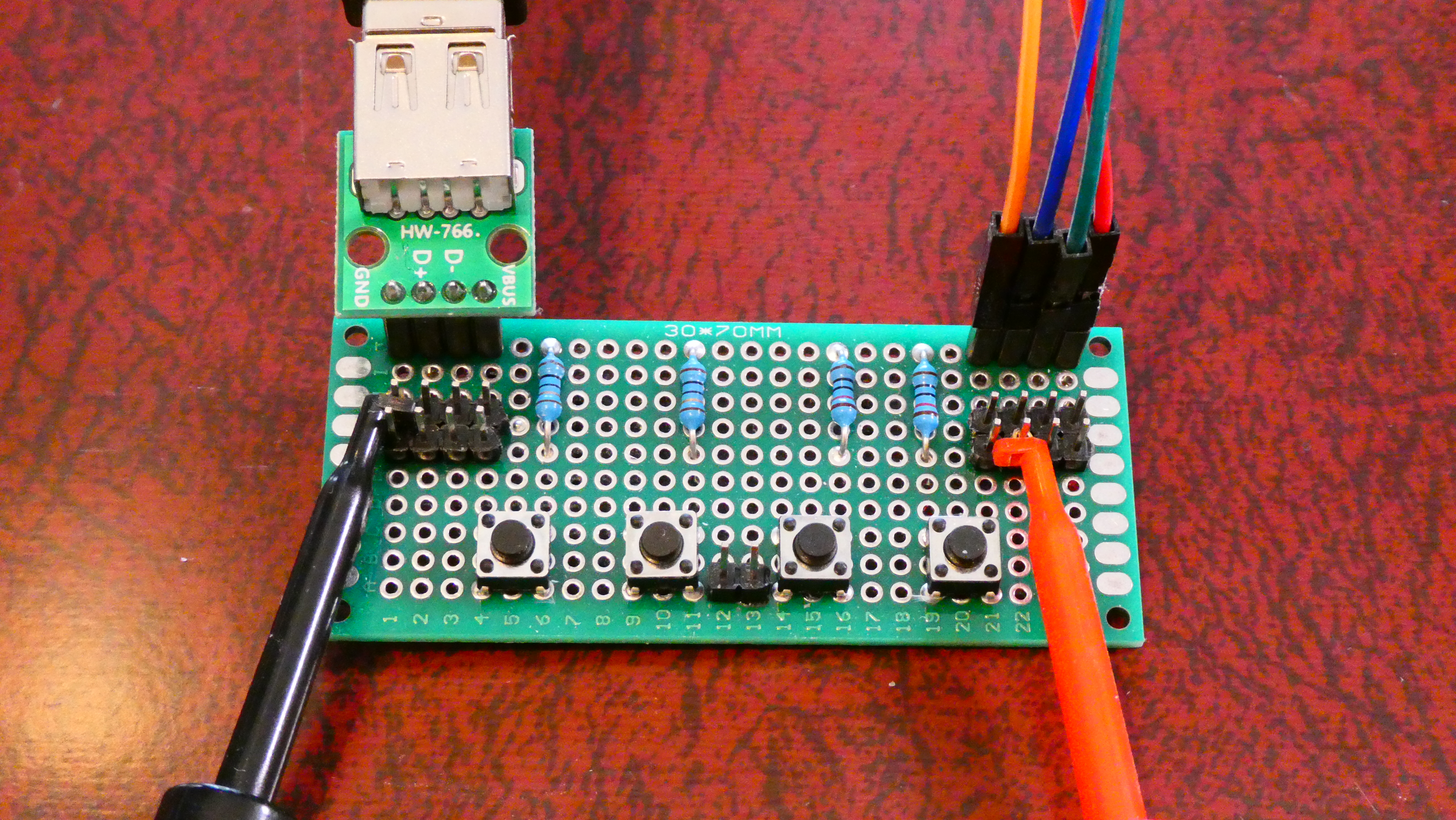
For the first board, debugging was achieved using a perforated board on which a USB connector can be plugged with a male-male USB cable to the connector, and the other end can be connected to the power pins of the Raspberry Pi Pico, while the data pins are connected where the microcontroller is supposed to be. These debugging board buttons are made to emulate pull-up and pull-down of the device on the data pins, and check what the voltage would be on the microcontroller side.
If you were to make this process scale, you might want to have a procedure for testing the board before soldering any through hole components, in order to keep some space around the components to rework the solder bridges. This implies being able to plug the select pins, data and power enable pins, 3.3V and 5V pins, but not the D+/D- pins that you want to keep for testing.
Once identified visually or electrically, reworking the QFN solder bridges is easy, as long as you have the right tools:
- Solder flux: The solder flux is used to reduce the surface tension of the solder, thus forcing it to make smaller droplets.
- Flat surface iron: The flat surface iron is used to provide an area where the surface tension is higher, such that it pumps the solder out of the solder bridge.
- Solder: The solder is used to pre-populate the flat surface of the iron with a tiny layer of solder, such that it can pull excess solder on the flat surface of the iron.
The procedure is simple: Apply some solder flux on the sides where there are the solder bridges, apply some solder on the flat surface of the iron, and slide the flat surface on the sides of the components where you have a solder bridge. That's all!
The Code
Building
This project might be the first (released) project which relies on Nix to develop code for the Raspberry Pi Pico using the Pico SDK, and additional libraries such as LwIP, Cyg43-driver, TinyUSB and Pico-PIO-USB.
Nix is a package manager, which is used by NixOS Linux distribution. It also
offers an experimental feature named flakes. While this feature is not as good
enough for managing all individual dependencies of a distribution, it is
excellent for language agnostic dependency management at the scale of a project,
similar to virtual-env in Python and npm in JavaScript.
While managing libraries this way introduces additional complexity, on top of CMake's strange composition rules, this makes managing dependencies reliable and potentially reproducible. The dependencies are all frozen to specific versions, which is good when you come back to a project after months, just to fix one annoying bug, and not a pile of integration issues.
In addition to providing the dependencies, this also helps building a working
environment. Using nix develop one would have a shell with a set
of shell functions for building, flashing and debugging the firmware.
Dependencies
This project mostly interacts with the following libraries:
-
Pico SDK with the Cyg43-driver are useful libraries which simplify the manipulation of the internal registers of the RP2040 and the Wifi component of the Raspberry Pi Pico W.
-
TinyUSB and Pico-PIO-USB are used to emulate a USB host.
-
FatFS library, included with TinyUSB, is helpful for manipulating files on a Mass Storage Class device. As UF2 protocol goes by as a fake Mass Storage device, this is mandatory.
-
LwIP to implement the web server stack. While technically not needed, this is nice for implementing some client side logic, and for working remotely on the device. Having 64 USB cables on one desk is going to be messy otherwise.
The Pico SDK is really well documented and is a pleasure to work with, even
macros have documentations, such as PICO_STDIO_USB_RESET_MAGIC_BAUD_RATE. This
feature implies that if you are using stdio_usb, the Pico can be switched back
to Boot-select mode by changing the Baud rate.
On the other hand, TinyUSB, LwIP, FatFS are lacking proper documentation. Even if LwIP has a doxygen-like documentation, it is not actionable without reading examples, reading the code and even enabling debug information.
Remapped UART Pins
The RP2040 has multiple UART outputs, if you want to make use of the other corner of the Pico for UART, this can be achieved as follows:
target_compile_definitions(uf2-batch-flasher PRIVATE
  PICO_DEFAULT_UART_TX_PIN=16
  PICO_DEFAULT_UART_RX_PIN=17
)
This might be useful if you already designed a board without even thinking about UART, and later realize that having any output is better than none.
Web based Stdout
On the other hand, once you have a working Web Server, you might as well use it.
The Pico SDK provides the stdio_driver_t structure to register handlers to
process inputs and outputs. Thus one could make use of it for additional use
cases, such as buffering everything which is generated by printf calls and
dump this content each time a file such as stdout.ssi is queried.
This feature is one of the most useful additions to this project, except when one freezes or locks the web server to a point where it does not answer anymore.
Testing with a single USB
Before designing the board, sometimes it is useful to validate the basics of the code. One example of it was to discover that setting the Baud rate to 1200 Hz was not enough.
While the USB device would properly switch to Boot-select mode, the TinyUSB library would not forget that the connected USB device was connected as CDC, and will not attempt to mount it as a Mass Storage device. Removing and restoring the power would reset the connected Pico and let it boot from the flash.
However, physically disconnecting the data lines and reconnecting them back proved to be effective as a way to force TinyUSB to unmount the CDC device and mount it as a MSC device.
Validating this part early also helps the design of the board, as we need both an enable power pin, but also an enable data pin.
Off-by-1 pin selections
Sometimes, what appears like a huge hardware mistake, is a simple software issue. When developing the initial version of the firmware, the select and enable pins got added, but one of the select pin got forgotten in the process. Thus instead of counting up to 64, it only counted up to 32.
The biggest problem with hardware and software development is that if you lack confidence in yourself or in your design, then you will always doubt that you made a mistake. Except that the mistake might be located where you are the most confident about your skills, and you lose an evening trying to look out for a bug at the location where it is not.
Naming RP2040 Pins
The picotool utility from the Pico SDK can read the content of a binary and
displays the strings which are stored inside it. Some of these strings can be
used to describe the GPIO functions:
void usb_gpio_init() {
  bi_decl_if_func_used(bi_program_feature("Select USB device"));
  init_select_pin(PIN_SEL0);
  bi_decl_if_func_used(bi_1pin_with_name(PIN_SEL0, "S0"));
  init_select_pin(PIN_SEL1);
  bi_decl_if_func_used(bi_1pin_with_name(PIN_SEL1, "S1"));
  init_select_pin(PIN_SEL2);
  bi_decl_if_func_used(bi_1pin_with_name(PIN_SEL2, "S2"));
  init_select_pin(PIN_SEL3);
  bi_decl_if_func_used(bi_1pin_with_name(PIN_SEL3, "S3"));
  init_select_pin(PIN_SEL4);
  bi_decl_if_func_used(bi_1pin_with_name(PIN_SEL4, "S4"));
  init_select_pin(PIN_SEL5);
  bi_decl_if_func_used(bi_1pin_with_name(PIN_SEL5, "S5"));

  bi_decl_if_func_used(bi_program_feature("Toggle USB device"));
  init_enable_pin(PIN_ENABLE_DATA);
  bi_decl_if_func_used(bi_1pin_with_name(PIN_ENABLE_DATA, "EN_Data"));
  init_enable_pin(PIN_ENABLE_POWER);
  bi_decl_if_func_used(bi_1pin_with_name(PIN_ENABLE_POWER, "EN_Power"));
}
In this case, bi_decl_if_func_used is simply a macro which declares a field in
a different section of the elf, named .binary_info. The code has nothing to do
with being used or not, it relies on the compiler to remove dead code. Thus,
UART pins would be listed there if stdio_uart_init is called. This is helpful
to verify that UART pins are correctly mapped and to verify that there is no typo
in the macro's name.
Then bi_1pin_with_name would declare a variable, which would hold on the
string content which can be queried by the command line tool.
The previous code would then display the following when using picotool info -p
on the UF2 image:
Fixed Pin Information
 0:   USB Host D+
 1:   USB Host D-
 2:   S0
 3:   S1
 4:   S2
 5:   S3
 6:   S4
 7:   S5
 8:   EN_Data
 9:   EN_Power
 16:  UART0 TX, UART0 TX
 17:  UART0 RX
Flush It
Ok, all the assignment pins are fine, there are no more solder bridges, a file is
created on a testing USB flash drive. Why would this file be of 0 size? You read
all the FatFS examples and you cannot figure out what is wrong with your code.
You call f_open, f_write and f_close, exactly like the example does.
This is where reading the code of the library and a bit of system knowledge
helps to remind you that f_sync looks like a promising function. Indeed, the
content might be cached on the USB drive but not yet committed to its final
destination. Calling f_sync ensures that the write persists.
LwIP: POST should not lock
However, writing content on the drive does not imply that this is the correct
content, and this is where the LwIP documentation is lacking. The throttling
mechanism for httpd_post_receive_data is confusing at best. One has to call
httpd_post_data_recved, but the code suggests that it should not be called with
more than what is received, while the calling it with what can be written to a
FIFO causes LwIP to lose most of the transmitted data.
When locking in httpd_post_receive_data, then data is simply lost and some
chunks are not received. Strangely, TCP is supposed to prevent messages from
being munched while in transit, by numbering the packets and verifying that all
packets are well transmitted in the right order.
At the end, just transmitting a clone of the struct pbuf and queuing this
allocation proved to work, despite getting closer to the RAM limits of the
RP2040. So far this works for UF2 images of 127 kB, but if a problem occurs, this
can be handled by writing files in multiple chunks and appending instead of
truncating existing files.
Strangely, once more the documentation of httpd_post_receive_data is slightly
confusing as the data should be freed, but even if it is not the struct pbuf
given as argument remains the same from one call to the next, actually causing
issues when freeing it. Also, additional cares should also be taken with struct pbuf as this managed by an allocation pool, and thus the allocation should be
returned to the web server core in order to free it properly.
Conclusion
This started as a tiny sub-part of a bigger project and at the end is much bigger than what was initially thought. Who would have thought that making one Raspberry Pi Pico flashing 64 others would face that many issues?
In the end, this remains a success. No more buttons to be pressed, 64 Raspberry Pi can be flashed remotely.
The Future
So far this project is a means to an end, but this might not be the end of the project. Much more could be achieved with this project, such as:
- Make the rest of the Pico pins available.
- Adding relays controlled by the Pico to turn all USB devices at once.
- Making it flashable from the command line, instead of the web interface.
- Improve the Web interface.
- Have a different images for specific ports.
- Patch a few bytes, to introduce small variations across all devices.
- Monitoring one of the devices using UART over USB.
If you are interested, you can find all the sources of this project on GitHub.
If you are interested in the final product, but not making one yourself, then beware that this is only the first version of it. And if despite this warning you still want one, send an email using the link below and we can discuss the details.